November 21, 2019

Procedure to Diagnose Issue When your Pellet Stove Control Panel Fuse Blows

Click here for additional info on pellet stove control panel failures,

When the control panel fuse blows, finding the cause may be very difficult so here are some steps to help pinpoint the problem 

1. Put in a new fuse on the control board/panel and time how many minutes or even seconds it takes from pressing the On button to when the fuse blows.This can help pinpoint which part may be causing the fuse to blow. If the fuse blows after just a few seconds, it may be a part that activates right at start up.
  When I performed this check for:
Customer1 - The fuse blew 7 seconds after pressing the On button, which indicated it may be the auger motor since it does not get power right away
Customer2 - The fuse blew immediately. This could be the exhaust blower or igniter causing the fuse to blow.However for a room blower it might take 15-20 minutes to blow the fuse. If you are still not sure which part is causing the fuse to blow, the four most common parts to cause this issue are the igniter, auger motor, exhaust blower, and convection blower.
2. Use an AC test cord and multi-meter to test how much current each of those parts draws. Start with the igniter as it is the most common part to cause this issue. Test the part in each step until you get a reading that is too high.
Click here to see the AC Test Cord


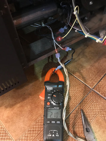
3.Take a good multi-meter and put the clamp around one of the igniter wires and plug it into the wall outlet with an AC test cord. It should read 2-3 amps. The multi-meter read 2.1 amps for customer1. See Pic 1 below. That was not too high (over the control panel fuse which is 5 amps in my case) so I continued testing other parts for customer1

For customer2 even though the igniter read 47 ohms with the ohm meter when plugged directly into the wall AC outlet, the igniter smoked up and one of the wires fell off! Replacing this igniter and the control board fuse fixed the issue and the stove worked fine. See pic 4 of bad igniter.

4. Using the multi-meter, plug the exhaust blower into the wall outlet with the clamp around 1 wire. At start up, it should read about 0.5 amps more than rated for on the motor tag. For my customer it read 1.5 amps for a 1.0 amp motor and then it settled down to 1.0 amp which is stamped on the Fasco motor tag. That was not too high so I continued testing other parts.

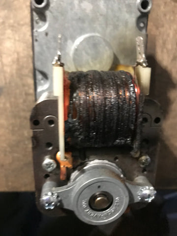
5. Using the multi-meter, plug the auger motor into the wall outlet with the clamp around 1 wire. It should read about what is stamped on the motor tag, which was 0.72 amps for my customer's auger motor. However when tested customer2 igniter, it read a whopping 10 amps and within seconds the windings caught on fire. This is very unusual. At 7 seconds when the fuse blew is when the auger started up! I replaced the auger motor and the stove was fixed! See pic 3 below.

6. If the control panel fuse does not blow for about 15 to 20 mins after the On button is pressed then there's a good chance the convection blower caused the fuse to blow. Using the multi-meter, plug the convection or distribution blower into the wall outlet with the clamp around 1 wire. It should read about 0.5 amps more at start up in my case 1.5 amps for a 1.0 amp motor and then settle down to 1.0 amps which is stamped on the motor tag.

Note: If you do not have a multi-meter and you have a few control panel fuses, usually 5 or 6 amps. Disconnect the igniter and then one motor at a time to see if the control panel fuse blows. It it does not blow then the one you just disconnected is bad and should be replaced.

7. If none of the motors draw excessive current then damage to the control board and blown fuses could be caused by power surges from the AC line at the wall outlet. Some examples are electrical storms, electric wires pulled off the house, power surges from generators activated with all breakers on, low quality noisy or dirty power or power fluctuations or brownouts, or unstable electric lines if the house is the last house on the street. This could slowly damage the control panel over 1-3 years! A good surge protector such as Tripp Lite to protect against voltage spikes or even better a Tripp Lite line conditioner for spikes and low voltage conditions can be a life saver for sensitive control panels.
Surge Protector
Tripp Lite UltraBlok Surge Protector
Line Conditioner
Tripp Lite Line Conditioner


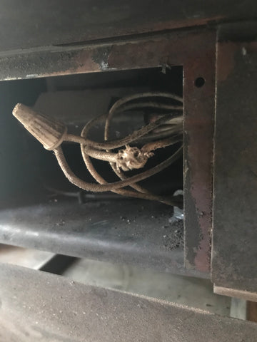
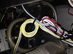
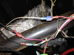
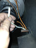
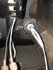
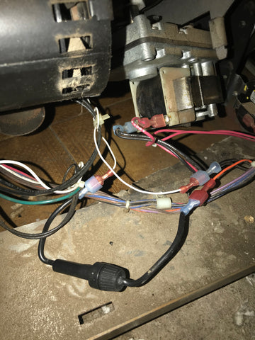
8. The wiring harness in the pellet stove has also known to cause the control panel fuse to blow if the insulation is cut and the bare wire is exposed and touching the metal body of the stove. In one documented case, the control panel was mounted on the side door that swings open and a bundle of wires hit the bottom metal stove edge because the holding clamp adhesive failed. A wire shorted out due to the pressure from the door closing. When the wire ties holding the bundle of wires together were cut, a simple inspection showed a cut in the insulation exposing bare wire. The owner did notice a spark when the side door was closed. In another case the high temperature ceramic wire nut fell off the igniter wire under the firepot and the exposed connection touched the body of the stove causing a short. See pic 5

When I followed the above procedure for my customers, I found the cause for customer1 at step 5 and customer2 at step 3. The solution was simply to replace the auger motor or igniter. If the parts in steps 1-5 draw too high a current, simply replace the part. If you get past step 5, an electrical short in the wiring harness or a surge in the electrical supply may have caused the control board fuse to blow.

Also when I ran the procedure for both my customers above,  the current that blew the control panel fuse did not blow the control panel. This may not always be the case, so if the stove does not work after replacing a bad motor or igniter and the blown fuse, then the control panel may also have to be replaced. See pic 2 below.


The igniter in these stoves draw the most current. Therefore it is highly recommended that if your stove does not have a separate fuse on the igniter, that an inline fuse holder with a Fast Blow Glass Fuse can be easily installed with a male and female quick disconnect clip crimped onto each end. Then it can be plugged into one of the igniter wires in the back of the stove. The correct amperage AGC fuse using E=IR can be easily calculated. For most 300 watt igniters, a 3 amp draw is calculated and another amp is added so any small fluctuation will not blow the fuse. Therefore a 4 amp fuse is sufficient. This will improve the safety of the control board so an igniter that shorts out will not blow the control board fuse and damage the control panel.

Note: These types of shorts can also trip and damage a GFCI outlet or breaker if the stove is plugged into one. After fixing the stove the GFCI may also need replacment.

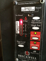
Pic 1 - Measuring the Igniter current draw

 Measuring the Igniter current draw

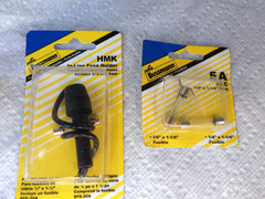
Pic 2 - Adding a 4 Amp Inline AGC type Fast Blow Fuse on your pellet stove Igniter to protect your Control Panel and Control Panel fuse

Adding a 4 Amp Inline AGC type Fast Blow fuse on your pellet stove Igniter to protect your Control Panel and Control Panel fuse

Pic 3 - Auger motor with burned out windings when tested!

Auger motor with burned out windings

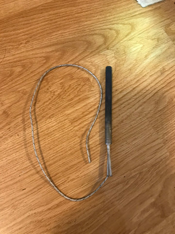
Pic 4 - Igniter drawing excessive current and burned one wire off when tested!

 Pic 5 - High temperature ceramic wire nut fell off of igniter wire connection and exposed wire shorted against the stove body under the firepot.


December 27, 2015

Pellet Stove Control Panels - How do they fail and why they need replacement? Also what bug fixes and enhancements do they have?

The hardest part in your pellet stove to diagnose and replace is without a doubt, the Control Panel.
Procedure to Diagnose Issue When your Pellet Stove Control Panel Fuse Blows 
Below is additional info for different pellet stove control panel brands
The control panel also known as the Circuit Board, Mother Board, LED panel, touch screen and Control Board can be very difficult to troubleshoot. In this article we will use the term control panel for simplicity. We will go over how they fail and what bug fixes and enhancements they have now for better stove performance! Also why you may want to upgrade!

Maybe the easiest way, is to take the control panel in question and put it in an identical known working stove and see if it works. This may be the best way but is certainly not possible in most circumstances. Therefore, I always check every other component in the stove and if they are all good, then the control panel may be bad. The next step to to analyze the environment and stove install for the second clue. Is the stove in a rural environment where power outages and power fluctuations known as brown outs more common? Does the home or building have whole house surge protection such as an Intermatic Whole House Surge protector or 2 surge protectors in the shape of circuit breakers installed in the circuit panel where the pellet stove outlet is plugged into? In the stove install, is there a good quality surge protector plugged into the AC wall outlet such as a Monster brand or Tripp Lite brand? We do not recommend the very inexpensive surge protectors that can be purchased at the big box stores or the local hardware stores. Also if a generator is used, it must be a pure sinewave generator such as a Honda so damage does not occur to the control panel. If there was no surge protection then a bad control panel is now more possible because the Triacs that switch the AC power are sensative to surges and can be damaged from them.

The last part of the control panel analysis process is knowing the known failures that these boards have and if any of these failures match up. Here is what I have found from my experience.

Components that do not turn on that have no safety switches connected to them point to a damaged control panel. So here are some examples that also help. The assumption here is all components were tested with a test cord to assure they are working and are connected properly and the connectors make a good connection. Many brands updated their control panels to be universal so they can be programmed for each mode. Also some panels have new features and bug fixes.

Just recently I have Replaced some bad Englander Control Panels. One board would not turn the exhaust blower on when the On button was pressed. Measuring the AC voltage at the connectors that were removed from the combustion blower showed 120 VAC but there was not enough current to start the blower going.  In this case the AC outlet was tested with an electrical circuit tester and found to have a phase reversal! The neutral wire and hot were reversed on the back of the outlet! After fixing the phase reversal in the AC wall outlet, a new Control Panel fixed the problem and of course a surge protector was added!  If the igniter does not light the pellets, it can be a bad control panel. Assure the pellets are dry and the igniter works.

Another case is when the Englander stove warmed up, in this case exactly 50 mins after the on button was pressed, All components ceased to function at the same time! In this case even though the heat sensor was good there board shut down the stove due to a false overheat trigger! In this case a new room blower was installed but you must assure the room blower is working properly and not clogged with dust.

Another example is the Pelpro Accutron II, III or IV Digital panels. They are not only sensitive to surges but if left plugged in when the side panels are removed, they can easily be shorted out and sparks can be seen! I witnessed this first hand and found that when the right side panel where the control panel is located was removed, the metal damper rod fell against the control panel, a big spark was seen and poof the control panel was no good! I have also seen burned components on the back of the board which also indicates a bad control panel. When these panels do not work, they may not light up, or fire the igniter or have other issues.


The Harman pellet stoves now have one control panel called a circuit board that fits all their models except the new touch screen. Even though they are sensitive to surges, if they live a long life the control knobs called potentiometers are known to develop flat spots or dead spots where there is no resistance causing the stove to no work or not work properly. I have also seen the fuse blown and a new fuse fixed the problem. In another case the fuse was blown but it would still not feed pellets after a new fuse was inserted. A new circuit board was the fix for that problem. Although the circuit boards have had many updates and bug fixes over the years if the stove is 5 to 10 years or more old, then I recommend replacing the control panel to get the better heat algorythms and updates.

Breckwell pellet stove control panels have been digital for many years. The earlier panels were made to turn the 4 RPM auger motors and 4 RPM augers and motors. After a few years they switched to 1 RPM auger, auger motor with a 1 RPM control panel. In one case I had to replace a panel because the stove was not giving off enough heat. I found that the room blower was not increasing it's speed for each heat level. The new panel fixed the problem. The newest Breckwell panel has the red background behind the Fuel Feed and On buttons, The older panel has a yellow background.

The Enviro control Panel is an example where the board was not only updated to fit most models but also has a new combustion blower trim button. In one case an Enviro Empress control panel was bad and not feeding pellets even though all safety switches were working. Again there was no surge protector on the stove.

The Napoleon was one of the last pellet stoves to get a digital control panel in it's new NPS45 and NPSI45. The latest version has quite a few bug fixes. In one case the pellets were not feeding with a new auger motor and the igniter was not lighting. A new control panel fixed the problem.


A Quadrafire Santa Fe that I picked up was not working at all. I found a burned out fuse in the 3 speed control box. Replacing the 7 amp fuse fix the problem.The new clear control box fixed a start up issue. The issue was not enough vacuum when the stove was below 30 degrees F when the heat level switch was on medium or low. The new clear control box always runs the the exhaust blower on high no matter what the heat level switch is set to during startup to fix the issue. If you have the old solid gray box you may want to upgrade.


In conclusion, there are many signs that point to a bad control panel and when no other part can fix the problem, then the control panel needs to be replaced.

December 25, 2015

Upgrading the Englander PU-CB98 to PU-CB04

The old Englander knob control panel and the Digital PU-CB98 Englander Control panels can be replaced by the Englander PU-CB04 control panel.

In the following example, I replaced an Englander Digital PU-CB98 Englander Control panel in a 2006 Englander 25-PDV. The old control panel on that stove increased and decreased the room blower speed with the exact same heat range number. The new panel allows the blower speed to be set higher from the heat range to provide better control and circulate more heat using less pellets.

The PU-CB98 shown below on left as well as the old knob control panels which are no longer made do not have any igniter connection.

Pic1 - PU-CB98 on left and PU-CB04 on right

Pic2 - PU-CB98 on left and PU-CB04 on right

Detailed Instructions from manual:

WARNING: STOVE MUST BE OUT (NO FIRE), COOLED DOWN, AND UNPLUGGED BEFORE PROCEEDING. FOLLOW ALL CODES.
NOTE: OLDER BOARDS (THOSE WITH TWO KNOBS AND TWO BUTTONS, INSTEAD OF THE TOUCH PAD) ARE WIRED DIFFERENTLY. THE NEWER STYLE BOARDS
WILL WORK WITH STOVES THAT USED THE OLD BOARDS; PLEASE STATE YOUR MODEL NUMBER AND DATE OF MANUFACTURE WHEN ORDERING.
1. If you are replacing an existing board, remove the rear access panel from the stove. Eight screws hold it in place. The
simplest way to change boards is to remove the wires one at a time from the old board and plug them into the new board; however, if
the old circuit board has already been removed, wiring a new one is quite easy. No solder joints are required, and the tools you will
need are very basic. You will need: a pair of cutting pliers; a 5/16” wrench or socket; and some zip ties (plastic wire ties).
Note: if your stove was manufactured before 2001, you will also need a 1/8” Allen wrench for the heat sensor screw.
2. The first step in replacing the old board is to remove the screw that holds the Heat Sensor in place. The sensor is located on
the left side of the feeder pot assembly (assy.), and is screwed into the firewall.
3. The next step is to unscrew the old circuit board from the side of the stove. Note: If your unit is an insert, remove the circuit
board mounting plate from stove with the board attached. There are two 5/16” screws that hold the board in place.
4. Looking at the back of the board (from left to right), the wires should be placed as follows: Terminals 1 and 2 are for the Convection (room air) Blower (this is the black blower located against the firewall to the left of the feeder pot assy.).PLEASE NOTE: “White/Black Rule:”If the component has a white and a black wire, the white wire should be plugged into the terminal marked “com” (Terminal 1 in this case), and the black wire should be plugged into the other terminal (Terminal 2 in
this case). If your component has two black wires, it does not matter which way they are placed.


5. The next two terminals (Terminals 3 and 4) are for the Upper Auger Motor, which is located in the center of the stove, mounted
to the feeder pot. Again, if there is a white and a black wire, the white wire should be plugged into “com” (Terminal 4) on your board; if
your motor has two black wires, it does not matter which way they are placed.
6. The wires for the Lower Auger Motor (again located in the center of the stove, under the Upper Auger Motor) should be
plugged into Terminals 5 and 6, and the above mentioned white/black rule applies, with the white wire (if present) plugging to Terminal
5 and the black to Terminal 6. NOTE: Term. 5 (marked “Lower”) is turned sideways to allow room for the top mounting screw.
7. Terminals 7 and 8 are for the Combustion (Exhaust) Blower. As always, the white/black rule applies, with the black wire
plugging into Terminal 7 and the white (if present) into Terminal 8.
8. The final two terminals (9 and 10) are for the Cartridge Heater Igniter (2004 or later). If your unit predates the Auto-Start Igniter
system, nothing is plugged into either of these terminals. If your stove is equipped with a Vacuum Switch, the wires for it connect to
the “J-2” terminals near the bottom of the board. An optional thermostat (part GU-1E30-914) would connect to the “J-3” terminals,
located beside the J-2 terminals.
9. Last, reinstall the new Heat Sensor to the hole that is located to the left of the feeder pot, and fasten the new board to the side
of the stove. Tie all of the wires in the back of the unit together, if they were cut free of the ties that were originally in the stove.
Important:
Tie the wires up in such a way as to prevent them from touching any electric motors or moving parts inside the stove!
10. After tying up your wires, plug the stove back in. Do not reach into the back of the stove after plugging it in! Turn the
stove on and visually check components for proper function. Remember that the Convection Blower will not come on until the stove is
at operating temperature, the Upper Auger Motor will run intermittently, and the Lower Auger Motor and Combustion Blower will run
continuously.
11. After confirming proper function, shut the stove down and unplug it from power, replace the rear panel, and reinstall the flue
system if it has been uninstalled.

June 01, 2014

Gauge Your Stove Voltages & Currents: Understand How it Functions.Test How it Operates


Remember when you used to have to install gauges in your car before they became standard? Pellet stove voltages and currents can be displayed in a similar manner, which helps you better understand how it functions and know what parts may need replacement. Why not use one for a pellet stove?
Though some new touch pads come with monitors that indicate voltage and current, few control panels do. Even if they do, you have to press a lot of buttons to get these readings. It makes it more complicated than it needs to be.This gauge works great, and it can always bee seen.

                         
There are many benefits to being able to gauge your stove's voltages and currents. One such benefit is operational testing for proper function. For example, you may find that a certain voltage level corresponds with how much air your room blowers distributes. A low voltage may indicate it is not blowing out enough air to make the room warm and it may need to be replaced. 

You will see in my photos that I hooked one up to the room blower. You may also use this gauge to measure the exhaust blower, auger motor, and ignitor. 115 VAC + or - 5 VAC means an exhaust blowing is running at full speed and is drawing less current. At low speeds, the exhaust blower draws more current (4 or 5 amp). Current that is much higher may be the sign the windings are shorting out.In the case of this Breckwell Big E, the normal voltage for the room blower on heat levels one and 2 measured 43 VAC, which means it is running 37% of full speed indicated by its fraction over 118 VAC.


Another issue is that your power company may not be supplying proper voltage. Look for 115 VAC + or - 5 VAC. If you are getting less than 110 VAC on a full setting, it is recommended to contact your power company. Your stove will not run properly if the supply voltage is too low.

Installation and operation:

After squeezing on the quick disconnect clips, installation is simple!
You should use wire ties to bundle up the wires. Keep the wires away from the hot spots, and it looks neater too. Initially, after starting up the stove, the gauge panel on a room blower will be blank. However, once the room fan starts, voila! You will see the panel background light up and the voltage and current numbers will appear.

After going through the room blower speeds, I discovered heat levels 1&2 have the same room blower speed and 4&5 have the same room blower speed on a Breckwell control board. You can learn a lot from using this component gauge.


Pellet stove component gauges can be found and purchased here, click here.


May 12, 2014

Fuse Install: When Ignitor Burns-out, Allow Manual Stove Start & Prevent Control Board Failure


When the igniter burns out, it often shorts out and blows the circuit board fuse or the house fuse. In either case, if the ignitor burns out it may damage the entire control board. The stove then loses power and cannot be started manually. If an ignitor burns out on a stove with a separate ignitor fuse, the control panel does not lose power and the stove can be started manually.

A high energy absorbing surge protector is also needed to protect the circuit board too and can be purchase here. > > http://www.eastcoasthearth.com/blogs/pellet-stove-parts-101/13522689-protect-your-pellet-stove-with-a-surge-protector-updated-wiring

Even if the stove comes with a circuit board fuse, a second fuse can be added to protect the control board. Losing power when the ignitor burns out will no longer be an issue! To illustrate this I'm using a Harman stove that I worked on, but what I'm about to show you will work in almost any stove. Look for the ignitor wire connected to the control board in your stove. It should be in the back. In the picture below, it is a yellow wire. This is where you will install an in-line fuse holder containing the new fuse. Please see the detailed step-by-step instructions below.

                    
An in-line fuse holder and quick disconnect spade lugs can be found and purchased seperately at your local hardware store such as Home Depot or Lowes. Some in-line fuse holders you purchase at a hardware store come with a 20 amp fuse. These are not effective. The fuse you install must be 5 amp if the circuit board fuse is 6 or 7 amp, or 4 amp if the circuit board fuse is 5 amp. You may order the correct fuse and holder in its entirety online here: click here. A crimping tool is necessary for a tight connection. A crimp kit with connectors may be purchased at a hardware store, but make sure the spade lugs are insulated. If not, they will easily short out against the stove body.

                      
Directions (Also see pics below)
1. Shut stove off and unplug from the wall. Assure no power going into the stove.
2. Crimp a male quick disconnect on one end of the fuse holder.
3. Crimp a female end on the other end of the fuse holder.
4. Insert the 4 or 5 Amp (Fast Blow) fuse in the fuse holder. Part # is AGC 4 or AGC 5
5. Disconnect one of the ignitor wires and clip in the new fuse holder.
Note:
On some stoves like Harman where the ignitor is connected with clips inside the air tube, it may be necessary to cut the ignitor wire closer to the control board to insert the fuse holder. Cut the ignitor wire where the fuse needs to be installed. Strip 1/4" off each end and crimp on 1 male and 1 female insulated quick disconnect.


April 09, 2014

Protect Your Pellet Stove with a Surge Protector & Updated Wiring


Connecting your pellet stove to a surge protector effectively protects digital control boards. I have mine connected to one at all times. They keep damaging surges caused by electrical storms or faulty wiring from cripling your pellet stove. Granted a large voltage spike from an intense electrical storm can immediately blow out a circuit board or control panel. However just like small doses of arsenic in humans, small voltage swings can create accumulative damage of time. In other words this damage can slowly poison the components in the control panel making it act flakey. This condition makes it very hard to diagnose the issue. For example, I worked on 2 Breckwell Big E pellet stoves. Great stoves that crank out alot of heat. Both stoves had no surge protection and after power fluctuations the room fan speed would no longer increase as the heat level was increased. The stove worked but did not put out much heat. After installing a new control panel the stoves heated like new again.

GFCI outlets are not needed for pellet stoves. The older pellet stoves ground design can actually keep tripping a GFI. I had a 1996 Breckwell P2000 that would not stay running on a GFCI.


Ground and polarity is also an important reason to consider using a surge protector. This is most relevant for older Whitfield Pellet Stoves which do not have a modern grounding design. They may have ground loops and be a shock hazard inside the stove. Not having a good ground polarity can be a real safety hazard. This can be checked with a simple polarity or phase tester.

The Breckwell Big E manual on Page 9 states what needs to be changed in an older home with a 2 wire outlet and no ground.
ELECTRICAL INSTALLATION
This stove is provided with a 6-foot grounded electrical cord
extending from the rear of the stove. We recommend connecting to
a good quality surge protector that is plugged into a standard threeprong,
120V, 60 Hz electrical outlet. Voltage variations can lead to
serious performance problems. The Breckwell electrical system is
designed for 120V AC with no more than 5% variation. Breckwell
cannot accept responsibility for poor performance or damage due to
inadequate voltage. If connected to an older, two-prong outlet, a
separate ground wire should be run to a proper ground (refer this to
a qualified technician).
 Always route the electrical cord so that it will
not come in contact with any hot part of the stove.

This grounding issue can be exemplified with our old Glenwood kitchen stove. It was an old 3 wire stove.It had two hot wires and a neutral also used as the ground. However, there was no complete wiring of the neutral to a common bus. The front mounted control panel had the neutral grounded to this metal panel so to complete the circuit, the current ran through the stove body! It seemed like a good design at the time. Also it may have saved manufacturing costs for not using the proper amount of ground and neutral wires!


The problem with this configuration is that as the stove got older, the screws that hold the front metal panel to the stove got very rusty! This resulted in a very poor electrical connection. One day my wife was wiping the counter with a sponge in one hand and coincidently  turned on the stove with the other hand. Current always flows through the path of least resistance and went right through her instead of those rusty old screws. Stove designers didn't realize that flaw back then. Thankfully she was ok, but I have heard of cases where people lose their eyesight from the current. The nerves in the eyes are like a weak filament in a light bulb.

The kitchen stoves we have today never run neutral to the stove body. That is why we have a 4 wire stoves. Another reason is if the neutral breaks connection and touches the stove body, the current still makes a solid run to the electrical box and not through us. It helps protect us from power surges and lightning.

Polarity was more important years ago for two prong household wiring and appliances (No separate case ground wire). If the polarity is reversed then the neutral and case of the appliance can become hot and give you a shock. This is the exact condition that trips a GFCI breaker! Back then household appliances such as hair dryers had metal cases instead of the plastic ones we see today. Pellet stoves still currently have a metal shell so polarity may still be an issue. If the polarity is incorrect, then the On/Off button which normally turns the power off where the hot line enters the stove, will disconnect the power upon exit. Even though the stove is off, there may be power in the stove that can cause a shock hazzard and give the wrong side of sensitive components on a digital circuit board a high potential. Even a surge protector cannot eliminate this safety hazard to you and hazard to the circuit board or control panel!

If you are looking for a surge protector, East Coast Hearth can help. Here are some links below to surge protectors and a Multi tester to help determine if your AC voltage is too high or too low.


There are two types of common surge protectors:

The standard surge protector dissipates up to 1,000 joules.

You can purchase it here with PayPal or a major credit card. Orders can also be called in by phone
http://www.eastcoasthearth.com/collections/pellet-stove-accessories/products/surge-protector-pellet-stove-defiant

The UltraBlok428 is the highest rated by absorbing up to 1,410 joules
You can purchase it here with PayPal or a major credit card. Orders can also be called in by phone
http://www.eastcoasthearth.com/collections/pellet-stove-accessories/products/tripp-lite-ultrablok-isobar-surge-protector-suppressor-2-outlets-direct-plug-in-1410-joules

Too high or too low AC line voltage can also create problems and keep your pellet stove from running right
The voltage should be 115 plus or minus 5 volts AC
You can easily measure this with our multi tester
You can purchase it here with PayPal or a major credit card. Orders can also be called in by phone
http://www.eastcoasthearth.com/collections/pellet-stove-accessories/products/ohm-meter-pellet-stove-tester-digital-multi-meter

March 18, 2014

Special Instructions for Replacing a Breckwell Ignitor


Here are some specific instructions for replacing a Breckwell ignitor. The ignitor shown in the photos is for the Breckwell Big E but the instructions are very similar for all other models.

 1. First, unclip the ignitor wires.

2. Next, remove the upper and lower bolts that hold in ignitor tube.

 3. Remove ignitor cartridge from tube with allen wrench.

4. Install ignitor cartridge into the ignitor tube.

5. Align ignitor cartridge in center of ignitor tube.

October 05, 2013

Pellet Stove Igniter Maintenance & Replacement : Do you have a spare?


I have sold and replaced many wood pellet stove ignitors that failed. Here are some tips on care and replacement and how to test for failure.

Obviously if the stove does not start on it's own anymore, then most likely the ignitor is bad, but here is really what to look for and how to make it last longer!

Remember the ignitor's job is to superheat the air coming into the ignitor tube. This hot air will set the pellets in the fire pot on fire.
To ignite corn the wattage of an Ignitor must be very high such as 525 watts. Otherwise most ignitors that are between 250 and 350 watts only light wood pellets. In the case of corn and a lower wattage ignitor, wood pellets must be used to start the fire.

1. Regular periodic maintenance called PM in our workshop. 

When doing your annual stove cleaning, it is good to pull the ignitor.
To do this, just unclip the electrical wires and use the correct wrench to loosen and remove the ignitor from it's housing.
See pics 1 & 2 (Magnum Baby CountrySide and other stoves use an open end wrench. Englander uses a socket wrench and other stoves use an allen wrench)

You can test the ignitor two ways
 a. Put a multi-meter on it and measure approx 40 to 50 ohms
 b. Use a AC test cord and plug the ignitor into the wall outlet, then check to assure it glows. See pic 3  (Be careful it does get hot enough to burn your skin!)

 If it does not light or measures infinity (Open Circuit) the ignitor should be replaced.
 See our web site pages for your ignitor replacement

 Just because the Ignitor works, it may not be good enough to light your pellets properly.
 Therefore you must also do the following.
 1. Clean the Ignitor
     I use a wire brush to remove any buildup and acetone to clean it off. (See pic 6)
     Since the Magnum Baby CountrySide igniter was straight, just cleaning it brought the startup time down to 6 min 30 secs and barely any smoke!
     It took much longer before cleaning and the firebox filled up with smoke!

 2. Check straightness and in tube alignment. If not straight or aligned there can be much more smoke during start up.

 Check the ignitor alignment and how straight the ignitor is. (See pic 4 & 5)
 The ignitor must reside in the center of the ignitor tube so if it does not then check the following:
 a. The ignitor is bent at the end and must be replaced
 b. The nut or bolt that holds the ignitor in must be loosened and ignitor straightened and the bolt be retightened.
     I have seen the alignment be off on the Englander 25-PDV and 25_PDVC units,
        so it takes a lot longer than 4 or 5 minutes to set the pellets on fire or not at all!

  Also do not forget to clean the ignitor tube and air inlet hole
  Clean the ignitor tube with a small bottle brush. (See pic 7)
  Clean the air inlet hole and/or air inlet hose with a pipe cleaner. (See pic 8)

As one final test to check the performance of your ignitor:
Time how long it takes from pressing the pellet stove's on button to the time the pellets ignite or fire starts.
Usually 4 to 5 minutes is really good but it can take up to 8 to 10 mins. It is best to check your time with another stove of the exact same make and model.

Since ignitors can burn out at anytime, like on a snowy cold weekend, it is great to have spare ignitor on hand.